
Vector diagram is a part of alternator, vector diagram is a simple diagram and this diagram we represented by arrows. and The vector diagram of loaded alternator have some important symbols that is E0 ,E ,V ,Z ,I etc. To know more about vector diagram read the article till the end.
The load on an alternator is varied its terminal voltage is also find to vary as in dc generator. This variation in terminal voltage is due to.
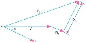
- Voltage drop due to armature resistance Ra . Which is in phase with armature current I.
- Voltage drop due to armature leakage reactance XL .
- Voltage drop due to armature reaction.
Click for what is current in electrical engineering
Armature reaction – alternator (Vector diagram of loaded alternator)
Armature reaction is the effect of armature flux on the main field flux. In case of alternator the power factor of the load has a considerable effect on the armature reaction.
So the three cases are : Unity power factor, zero power factor lagging, zero power factor leading which are explain below.

1. Unity power factor
In this case the armature flux is cross magnetising. So the result is that the flux at the leading of the pole is reduce while it is increase at the trailing tips.
So these two effect nearly offset each other leaving the average field strength constant. Hence, The armature reaction for unity power factor is distortional.
2. Zero power factor lagging
In this case the armature flux is in direct opposition to the main flux.
Hence, the main flux is decreased. And the armature reaction is demagnetising , due to which the main flux is weak and less E.M.F. is generate.
3. Zero power factor leading
So In this case armature flux will moved forward by 90° so, that it is in phase with the main flux wave.
This result in added main flux .hence in this case ,armature reaction is magnetising ,which result in greater induced E.M.F.
4. Intermediate power factor
For intermediate power factor the effect is partly distortional and partly demagnetising because the power factor is lagging.
See also this what is a 3 phase induction motor
Synchronous impedance

For the same field excitation terminal voltage is decrease from its no-load value Eo to V. Because of
- Drop due to armature resistance ( IRa )
- Drop due to leakage reactance ( IXL )
- Similarly, drop due to armature reaction.
The drop in armature voltage due to armature reaction may be accounted by the presence of reactance Xa in the armature winding. So the leakage reactance XL and the armature reactance Xa may be combine to give synchronous reactance Xs .
Hence, Xs = XL + Xa the total voltage drop in an alternator under load = IRa + jIXs = I( Ra + jXs ) = IZs
| IRa = Armature resistance |
| IXL = Leakage reactance |
| Xa = Armature reactance |
| Xs = Synchronous impedance |
| Eo = Is the no-load value |
| V = Is the terminal voltage or rated voltage |
Voltage regulation of an alternator – (Vector diagram of loaded alternator)
The voltage regulation of an alternator is defined as the rise in voltage when full-load is removed divided by the the rated terminal voltage.
So % regulation ‘up’ is
So The change in terminal voltage of an alternator depends on load on the load power factor.
| NOTE : E0 − V is the arithmetic form |
For what is the relation between torque and rotor power factor
What are the methods of determining voltage regulation?
So There are different types of methods of determining voltage regulation and they are direct loading method, synchronous impedance or E.M.F. method, the ampere turn M.M.F. method,
zero power factor or potier method.
But here we consider only two method, which are explain below.
Direct loading method – (Vector diagram of loaded alternator)
The alternator is driven at synchronous speed and the terminal voltage is adjusted to its rated value ‘V’. and The load is varied until the wattmeter and ammeter indicates the rated value at desire power factor.
The entire load is thrown off while the speed and field excitation are kept constant. The open-circuit or no-load voltage E0 reading is taken. hence, regulation can be found from % regulation
Synchronous impedance or E.M.F. method – (Vector diagram of loaded alternator)
This method requires
- Armature Resistance (Ra) or stator resistance (Ra).
- Open-circuit or no-load characteristic.
- Short-circuit characteristic.
(i) Value of Ra
Armature resistance Ra can be measure directly by volt meter and ammeter method or by using wheatstone bridge or multimeter.
(ii) Open-circuit characteristic
In D.C. machine this is characteristic plotted by running the machine on no-load and the reading of induced voltage and field excitation current.
(iii) Short-circuit Characteristic
It is obtained by short-circuiting the armature winding through the low-resistance armature. The excitation is so adjusted to give 1.5 to 2 times the value of full load current. During this time, the speed is kept constant.
See also this what is alternator in electrical
Procedure for synchronous impedance method – (Vector diagram of loaded alternator)
- open-circuit characteristic is plotted and the terminal voltage or induced voltage ‘v’ and field excitation current or no-load current If .
- Then Short-circuit characteristic is plotted it is a straight line passing through the origin. and Bothe these curve are drawn on a common field-current base.
- Consider a field current If the open circuit voltage corresponding to this field current is E1 when winding is short-circuited, the terminal voltage is zero.
- Hence, The whole of this voltage E1 is being use to circulate the armature short-circuit current I1 again the synchronous impedance Zs.
E1 = I1Zs
Since Ra can be found by the formula
![]()
5. So Knowing the value of Ra and Xs vector diagram can be draw for any load and any power factor.

OD = E0
∴ ![]()
![]()
So % regulation ‘up’ is =
![]()
Some numerical and solution from Vector diagram of loaded alternator
Question-1 : A 3-phase star-connected alternator supplies a load of 10 MW at power factor 0.85 lagging and at 11 kv terminal voltage. and its resistance is 0.1 ohm per phase and synchronous reactance 0.66 ohm per phase. So calculate the line value of e.m.f. generated.
Solution :
Given data
(1) Power factor – 0.85
(2) Load – 10 MW
(3) Terminal voltage – 11 KV
(4) Resistance ( Ra ) – 0.1 ohm
(5) Synchronous resistance ( Xa ) – 0.66 ohm
Full load output current = 10 × 106 / √3×11×103×0.85 = 617.5 ≃ 618 A
IRa = 618×0.1 = 61.8 volt
IXs = 618×0.66 = 407.8 volt
Terminal voltage = 11,000 / √3 = 6350.8 volt
Cos Φ = 0.85
Φ = Cos−1 (0.85)
Φ = 31.78
So the value of Sin Φ = 0.526
![]()
![]()
E0 = 6622.78 volt
Therefore line voltage is = √3 × 6622.7 = 11480 volt
For what is resistance ? in electrical
Question-2 : The effective resistance of a 2200V, 50Hz, 440 KVA, 1-phase, alternator is 0.5 ohm. On short circuit, a field current of 40 ampere gives the full load current of 200 ampere. and the electromotive force on open-circuit with same field excitation is 1160 V. So Calculate the synchronous impedance and reactance.
Solution :
Given data
(1) Power =440 KVA
(2) Voltage = 2200 V
(3) Frequency = 50Hz
(4) Ra = 0.5 ohm
(5) I.S.C. = 200 A
(6) V.O.C. =1160 V
Zs = E1 / I1 = 1160/200 = 5.8 ohm
![]()
![]()
So Synchronous reactance is = 5.77 ohm
Question-3 : A 60 KVA, 220V, 50Hz, 1-phase alternator has effective armature resistance of 0.016 ohm and an armature leakage reactance of 0.07 ohm Compute the voltage induced in the armature when the alternator is delivering rated current at a load current at a load power factor (i) of a unity (ii) 0.7 lagging (iii) 0.7 leading.
Solution :
Given data
(1) Power = 60 KVA
(2) Voltage = 220 V
(3) Frequency = 50 Hz
(4) Ra = 0.016 ohm
(5) XL = 0.07 ohm
Full load current = 60×103 / 220 = 272.72 A
IRa = 272.72 × 0.016 = 4.3 V
IXL = 272.72 × 0.07 = 19 V
(i) Unity power factor
![]()
![]()
(ii) Power factor – 0.7 (Lagging)
![]()
![]()
So how to find out the value of Sin Φ
CosΦ = 0.7
Φ = Cos-1 (0.7)
Φ = 45.57
So Sin Φ = 0.7
(iii) Power factor – 0.7 (Leading)
![]()
![]()
So the phasor diagram is

Question-4 : In a 50-KVA, star-connected, 440-V, 3-phase,50Hz alternator, the effective armature resistance is 0.25 ohm per phase. and The synchronous reactance is 3.2 ohm per phase and leakage reactance is 0.5 ohm per phase. Then determine at rated load and unity power factor . (i) Internal e.m.f. Ea (ii) no-load e.m.f. Eo (iii) percentage regulation on full-load (iv) value of synchronous reactance which replace armature reaction.
Solution :
Given data
(1) Power – 50 KVA
(2) Voltage – 440 V
(3) Frequency – 50 Hz
(4) Ra – 0.25 ohm
( 5) Xs – 3.2 ohm
(6) XL – 0.5 ohm
Voltage (V) = 440 / √3 = 254.03 ≃ 254 V
Full load output current = 50×103 / 440×√3 = 65.6 A
Voltage drop ( IRa ) = 65.6 × 0.25 =16.4 V
Voltage drop across synchronous reactance ( IXs ) = 65.6×3.2 = 209 V
And voltage drop across leakage reactance ( IXL ) = 65.6×0.5 = 32.8 V
(i) ![]()
![]()
Hence line value is = √3×272 = 471 volt
(ii) ![]()
![]()
So the Line value is = √3×341.7 = 591.8 volt
(iii) % regulation =
![]()
![]()
= 34.52 %
(iv) Xa = Xs – XL = 3.2 – 0.5 = 2.7 ohm
So Phasor diagram is

In the above article we study about vector diagram of loaded alternator so friends, what we learned from this article? How to make vector diagram and phasor diagram, how to make it in 3 different case (1st unity 2nd lagging and 3rd leading). And also we learned some important formula. Hope you like this article and know more information then please comment. share to your friends, Thank you.