
A. C. generator are known as alternator. Which operates on the same principle of electromagnetic induction as D. C. generator. It consist of an armature winding and a magnetic field. But it’s arrangement is reverse of D.C generator that is armature winding is mount on a stationary element called stator. And field winding on a rotating element called rotor.
In alternator or generator the stator consist of a cast-iron frame, which supports the armature core, having slots on its inner periphery for housing the armature conductor. So the rotor is like a flywheel having alternate North and South pole fixed to its outer rim.
When the rotor rotates , the stator conductors are cut by the magnetic flux , hence they have induced E.M.F produce in them. Because the magnetic poles induce an E.M.F and hence current in armature conductor. Which first flow in one direction and then in other.
Hence, an alternator or generator is produce in the stator conductor whose frequency depends on number of North and South poles and whose direction is give by Fleming Right-hand rule.
See also this vector diagram of loaded alternator
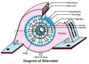
Construction of an alternator
Stator Frame
In D.C machine the outer frame serves to carry the magnetic flux but in case of alternator , it is use for holding the armature winding in position, so the armature winding stay in position and the Cast iron is require to make the stator frame or mild steel having a box type section.
Stator core
Stator core is the armature core supported by the stator frame and is built up of lamination of special magnetic iron or steel alloy. Lamination of the core is necessary for minimize losses due to eddy current.
Rotor
The revolving field structure is usually known as rotor. So there are two types of rotor construction and they are Salient-pole type rotor, Smooth Cylindrical type rotor.
( 1 ) Salient pole type rotor
Salient-pole type rotor is use in low and medium speed alternator. So, it has a large number of projecting poles with their core bolted. They have large diameters and short axial length.
The pole and pole-shoes are laminated to minimize heat. Because the heat produce due to eddy current. And the winding is make by copper strip.
( 2 ) Smooth cylindrical rotor
In steam turbine alternator smooth cylindrical type rotor is use because, it runs high speed and it is use specially for turbo alternator.
The rotor consist of smooth solid forged steel cylinder and having a number of slots at intervals. Because this rotor are design for 2-pole or 4-pole turbo alternators and running at 3600 rpm. So, it has small diameter and very long axial length.
See also this what is resistance ? in electrical
Define damper winding
In the pole shoes of an alternator consist of slots to receive copper bars and the copper bars are short-circuited at both of ends by heavy copper rings. So, this bar is call damper winding.
Which are use to prevent the hunting speed fluctuation and it maintain balance 3-phase voltage under unbalance load condition in an alternator and are need in synchronous motor to provide the starting torque.
So, in normal running condition damper winding does not carry any current because, the rotor runs at synchronous speed.
What are The advantages of stationary armature and rotating field system
- The out put current can be allow to flow directly into the load circuit from the fixed terminal of the stator, without passing it through the brush contact.
- And it is easier to insulate stationary armature winding for high voltage.
- The armature winding can be easily deform without any fault , such as short circuit fault etc.
See also this what is the relation between torque and rotor power factor
Relation between speed and frequency
Let P = Number of magnetic poles
N = The speed of the rotor in rpm
F = frequency of the generated E.M.F
Consider the armature conductor situated at the center of north pole and rotating in clockwise direction. The conductor at place of maximum flux density hence the E.M.F induced in it is maximum. So the direction of induced E.M.F is given by Fleming Right Hand rule.
So when Applying Fleming right hand rule
But, while applying this rule the thumb indicates the direction of motion of the conductor relative to the field. Therefore, while absorbing on the clockwise revolving pole, the conductor seem to be rotating anti-clockwise and the thumb should point to the left.
The direction of induced E.M.F is downward in a direction at right angle to the plane of the paper. When the conductor is in the interpolar gap, it has minimum E.M.F induced in it, because flux density is minimum.
Again, while rotating the conductor position is at the center of the south pole it has maximum E.M.F induced in it , because the flux density at ‘B’ is maximum. But, the direction of E.M.F when conductor is over a north-pole is opposite to that when it is over a south-pole.
One cycle of E.M.F is induce in the conductor when one pair of pole passes over it. In other words, the E.M.F in an armature conductor goes through one cycle in angular distance equal to twice the pole-pitch.
Since one cycle of E.M.F is produce when a pair of poles passes a conductor, the number of cycle of E.M.F produce in one revolution of the rotor is equal to the number of pairs of poles.
Therefore, Number of cycle /revolution = p/2
And Number of revolution/ sec = N/60
Frequency = Number of revolution / sec =
![]()
![]()
![]()
Where, ‘N’ is know as the synchronous speed, because it is the speed at which an alternator or a generator must run, in order to generate an E.M.F of the required frequency.
Referring to the above equation , So we get
![]()
So lets see how to find out rotor speed ‘N’
Example :-
| No. of Poles | N |
| 2 | 3000 |
| 4 | 1500 |
| 6 | 1000 |
| 8 | 750 |
We know ,
![]()
P = 2 , f = 50
(1) N = 120×50/2 = 3000 r.p.m.
(2) N = 120×50/4 = 1500 r.p.m.
(3) N = 120×50/6 = 1000 r.p.m.
(4) N = 120×50/8 = 750 r.p.m.
| P (Pole) is inversely proportional to speed | P ∝ 1/N |
| And speed is directly proportional to frequency | N ∝ f |
| Pole is directly proportional to frequency | P ∝ f |
E.M.F. equation of alternator – induced E.M.F.
Let, Z = Is the number of conductor
P = Is the number of pole
Φ = flux/pole
N = Speed in rpm/speed of the rotor
Kd = Distribution factor
A = Is the number of parallel path
Kp or Kc = Pitch factor or coil span factor
N = Speed in rpm/speed of the rotor
Kf = From factor = 1.11 [If E.M.F. is assumed sinusoidal]
Therefore In one revolution of the rotor, that is N/60 second each stator conductor is cut by a flux of ΦP
therefore, dΦ =ΦP and dt = 60/N
Therefore the average E.M.F induced per conductor is
![]()
We know that, F = PN / 120 or N = 120f / P
Substituting the value of ‘N’
So we know the formula of rotor speed, N = 120f / P
![]()
Now put the formula of rotor speed, so we get
![]()
So, average E.M.F. per conductor = 2fΦ volt. If there are Z number of conductor in series per phase, then average E.M.F. per phase = 2fΦZ volt.
Where, T is the number of coil per phase =2 Φ f
Z = 2 Φ f Z
Z = 2 Φ f 2 T
So the total value of Z will be
Z = 4 Φ f T
R.M.S. value of e.m.f. / phase
= 1.11 × 4 fΦT
= 4.44 fΦT Volt
This would have been the actual value of the induced voltage if all the coils in a phase were full pitched and concentrated or bunched in one coil.
Therefore, this not being so, actually available voltage is reduce in the ratio of two factors that is actually available voltage per phase = 4.44 Kd Kc f Φ T or = 4 Kf Kd Kc f Φ T volt.
If the alternator is star connected then the line voltage √3 time to the phase voltage .
See also this what is a 3 phase induction motor
Armature winding in alternator
The armature winding in alternator are different from those used in D.C. machine. So, the D.C. machine have closed circuit winding but alternator winding are open.
In the sense that there is no closed path for the armature currents in the winding it self one end of the winding is join to the neutral point and the other is brought out for a star connected armature.
So there are two types of armature winding most commonly used for three phase alternator are , (1) Single layer winding (2) Double layer winding.
Single layer winding

There are 12 slots in a 4 – pole, giving 3 slots per pole or 1 slots per phase per pole the pole pitch is 3 to get maximum E.M.F. two sides of a coil should be one pole pitch apart that is coil span should be equal to one pole pitch.
In other words if one side of the coil is under the center of a north pole then the other side of the same coil should be under the center of south pole that is 180°. In that case the E.M.F. induced in the two sides of the coil are add together.
The ‘R’ phase starts at slot number 1, then phase through slot 4,7 and finishes at 10. The Y-phase starts 120° afterwards that is from slot number 3 which is two slot away from the start of ‘R’ phase, because when 3 slots correspond to 180° electrical degrees,
Then 2 slots corresponds to an angular displacement of 120° .It passes through slot 6,9 and finishes at 12. Similarly B phase starts from slot number 5 that is two slots away from the start of Y-phase .
So it passes through 8,11 and finishes at slot number 2. and the ends of the winding are joined to form a star connected at a star point.
Short pitch winding in alternator
Let Es = be the induced E.M.F. in each side of the coil.
If the coil is full – pitch the total E.M.F. induce = 2Es .
If the coil is short pitch by 30° then the resultant of the two vectors sum of the two voltage 30° apart. So is the resultant E.M.F. induce.
![]()
= 2ESCos150
= 2 × 0.965 ES
So KP = Vector sum / Arithmetic sum
= 2ESCos150 / 2ES = Cos150 = 0.965

Hence, the pitch factor is 0.965 (It is always less than unity.)
Note : KC / KP = Cos( α/2 )
Distribution or breadth factor or winding or Spread factor or breadth factor
E.M.F. with concentrated winding = Es + Es + Es = 3S.
E.M.F. with distributed winding
E = ES +ES Cos 20° + ES Cos 20°
E = 2ES Cos 20° + ES
E = ES ( Cos 20° + 1 )
E = ES × 2.878
E = ES × 2.88 = 2.88 ES
So Kd = 2.88 ES / 3 ES = 0.96 ES

Let ‘β’ be the angular displacement between the slots.
Therefore β = 1800 / Number of slots per pole
β = 1800 / n
m = Number of slots/phase/pole
mβ = Phase spread angle or distribution angle
AB = ES
ES = 2r Sinβ /2
Arithmetic sum = mES
Vector sum = AE
![]()
So Kd = Vector sum of coil e.m.f / Arithmetic sum of coil e.m.f

![]()

So the formula for the distribution factor ‘Kd‘ is

Some numerical and solution
(1) Calculate the distribution factor for a 36-slots, 4-pole, single layer 3-Φ winding ?
Solution :
Given data
(1) Number of slots = 36
(2) Pole = 4
(3) Single layer 3-Φ winding
(i) We know , N = Number of slots / pole
= 36 / 4 = 9
(ii) β = 1800 / n
= 1800 / 9 = 200
(ii) m = Number of slots/pole phase
= 36 / 4×3 = 3
(iv) Distribution factor ( kd )

(2) Find the value of kd for an alternator or a generator with 9 slots per pole for the following cases : (i) One winding in all the slots (ii) One winding using only the first 2/3 of the slots/pole (iii) Three equal winding placed sequentially in 60° group.
Solution :
So we know that, N = is the number of slots/pole and N = 9
But in case (i) and (ii) the value of ‘m’ that is number of slots, So we will take m = 9 and case (iii) m = 3.
Case (i) m = 9
β = 180° / 9 = 20°
Case (ii) m = 9×2 / 3 = 6
β = 180° / 9 = 20°
Case (iii) m = 3, β = 180° / 9 = 20°
(3) A part of an alternator winding consists of 6 coils in series, each coil having an E.M.F. of 10 volt R.M.S. induced in it. The coil are placed in successive slots and between each slot and the next, there is an electrical phase displacement of 30°. Find graphically or by calculation . The E.M.F. of the coil in series.
Solution :
By calculation method
β = 30° , m = 6

Arithmetic sum of voltage induced in 6 coil = 6×10 = 60 volt
So Vector sum of e.m.f. = kd × Arithmetic sum
= 0.64×60
= 38.4 volt
So i hope you must have got a lot of interesting information from our article alternator. share to your friends, Thank you.