
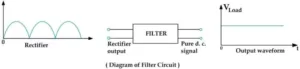
Filter is an electronic circuit which converts the pulsating d. c. signal into pure d. c. signal. In other way, A filter circuit is a device which removes the a. c. components to d. c. to reach the load.
A filter circuit is generally a combination of inductor ( L ) and capacitor ( C ). The capacitor passes a. c. but does not pass d. c. components An inductor opposes a. c. but allows d. c. to pass through it.
Click For What is rectifier in electronics ?
Click For What is transistor in electronics ?
What is the need of filter circuit
Before knowing why we need a filter circuit, we need to know what is rectifier? so as you know, Rectifier is an electronic device which converts alternating current ( a. c. ) into direct current ( d. c. ).
In the case of rectifier we get d. c. at the output, when we apply a. c. to the input. The direct current we get at the output is not pure direct current, it is a pulsating d. c.
Means there are some a. c. components along with d. c. ( AC + DC ). So a filter circuit is used to remove unwanted components. There are different type of filter circuit a rounding to their construction.
Types of filters in electronics
There are four types filter, but the most commonly used filter circuits are (1) capacitor filter (2) choke input filter (3) capacitor input filter.
- Inductor filter or ( series inductor filter )
- Capacitor filter or ( Shunt filter )
- Choke input filter or ( LC filter )
- Capacitor input filter or ( π filter )
Now we will discuss about the filter one by one, So let’s start
What is inductor filter? or ( series inductor filter )
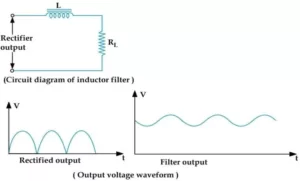
It consist of an inductor (L) placed across the rectifier output in series with the load resistance. The inductor filter is also known as series inductive filter because the inductor is connected in series with the load resistance RL.
When current passes through an inductor it provides a high resistance to the a. c. component and low resistance to the d. c. So the inductor blocks a. c. component and only pass d. c. component to the load.
What is a capacitor filter ? or ( Shunt filter )
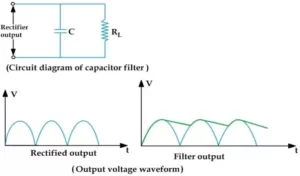
It consists of a capacitor ( C ) placed across the rectifier output in parallel with load RL. When pulsating d. c. signal is apply to the input of the filter, the capacitor will block.
The d. c. components and it will pass the a. c. component through it. Hence, we will get a pure d. c. signal at the output ( RL ).
The capacitor filter circuit is extremely popular because of its low cost, small size, little weight and good characteristics.
What is choke input filter ? or ( LC filter )
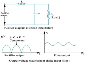
It consists of a choke ‘L’ (Inductor) connected in series with the rectifier output and a filter capacitor ‘C’ connected parallel with the load resistance RL.
The inductor (L) will pass the d. c. component of the input signal and it blocks the a. c. components. The signal which is passed from the inductor (L) still contains little amount of a. c. component.
When this signal is reaches the capacitor it will block the d. c. component and passes the a. c. component. Therefore we get only d. c. signal at the output of the filter.
Capacitor input filter circuit or ( π filter )

The circuit consists of a capacitor C1 connected across the rectifier output, a choke inductor (L) in series and another capacitor C2 connected across the load.
The filter capacitor C1 , the capacitor C1 blocks the d. c. components which should pass through the inductor (L) and by passes the a. c. component present in the rectifier output.
The choke inductor (L) blocks the a. c. components and allow to pass the d. c. components and the output of the inductor (L) again passes through the capacitor C2 .
Again its blocks the d. c. components and by passes the remaining a. c. components. The block d. c. components passes through the load and a power d. c. is obtain across the load.
So friends, what did you learn from this article ? You learned that by removing AC component you will get only DC in the output that’s why we use filter circuit. And also get to know the function of 4 different types of filter.
Hope you will get a lot of information from this topic, Thank you.