
What are induction motor, we read in the previous article, But do you know what is plugging in induction motor what are power stage and how torque is develop and how a induction motor operating as a generator. So in this article we are going to read all this. And also we solve some numerical. So let’s start this topic.
What is plugging of induction motor
An induction motor can be stop quickly by interchanging either of its two stator leads. This reverses the direction of the revolving flux which produces a torque in the opposite direction, thus applying the brakes on the motor this is also called plugging of an induction motor in this period the motor acts as a brake.
It absorb kinetic energy from the revolving load causing its speed to falls.
Read also this What is a 3-phase induction motor
Read also this What is resistance in electrical
Induction motor operating as a generator
When induction motor run faster than a synchronous speed. It runs as a generator called a induction generator.
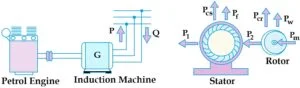
It converts the received mechanical energy into electrical energy and this energy is release by the stator. As soon as the speed of the motor exceeds its synchronous speed. and It starts delivering the active power ‘P’ to the three phase line for creating its won magnetic field.
It absorbs the reactive power ‘Q’ , from the line to which it is connect then ‘Q’ flow in a direction opposite to ‘P’. So the active power is directly proportional to the slip above the synchronous speed.

Power stages in induction motor

The loss of the stator iron depends on the supply frequency and the flux density in the iron core. hence It is practically constant.
The iron loss of the rotor is negligible because the frequency of the rotor current is always small under normal running conditions. So total rotor cu loss is = 3I2R. [Where cu means copper ]
Torque developed by induction motor


An induction motor develop gross torque ‘Tg‘ due to gross rotor output ‘Pm‘. and Its value can be expressed either in terms of rotor input power P2 .
The shaft torque Tsh is due to output power Pout which is less than Pm due to frictional loss and windage loss in the motor. and The difference between Tg and Tsh is equals to torque loss.
Due to friction and windage loss in the motor so, the N and Ns are in r.p.s. However , if they are in r.p.m. the expression for motor torque change to
![]()
![]()
![]()
Read also this vector diagram of loaded alternator
Torque, Mechanical power and Rotor output
Stator input = P1 = ( Iron loss + Cu loss) [Where , Iron loss = Stator loss and ‘Cu’ means copper]
So we can say P1 = ( Stator output + Stator losses)
Stator output is transfer inductive load to rotor circuit.
Therefore P2 = Stator output
Rotor gross output, Pm = P2 − rotor loss
This rotor output is convert in to mechanical energy and the gross torque gives rise to Tg, Some of the developed gross torque is lost due to windage and friction loss in the rotor and the rest appear as shaft torque Tsh .
Tg × 2πN = Rotor gross output Pm
Therefore Tg = Pm/2πN
If there were no Cu losses in the rotor, then rotor output will be equal to rotor input and the rotor will run at synchronous speed, then the equation will become.
Tg = Pm / 2πN …………. equation (1)
Tg = P2 / 2πNs …………. equation (2)
So From equation (1) and (2) we get
Rotor gross output = Pm = Tg ω = Tg 2πN
Rotor input = P2 = Tg ωs = Tg 2πNs ………… equation (3)
The rotor Cu loss is the difference of rotor input and rotor output
Therefore rotor Cu loss = P2 − Pm
Rotor Cu loss = Tg 2πNs − Tg 2πN
= Tg 2π(Ns − N) ………… equation (4)
= Tg 2πs ………… equation (4)
Therefore from equation (3) and (4)
Rotor Cu loss / Rotor input = Tg 2π(Ns − N) / Tg 2πNs
= Ns − N / Ns
= s (Slip)
Therefore rotor Cu loss = s×P2 (Rotor input) ………. equation (5)
Also , rotor input P2 = Rotor Cu loss / s
Rotor gross output Pm = Rotor input − Cu loss
Pm = P2 − s×P2
Pm = P2 (1−s) ………. equation (6)
So , Pm / P2 = (1−s) and (1−s) = N/Ns [ N/Ns is rotor efficiency ]
| So , Pm / P2 = N /Ns |
| Then Rotor Cu loss / Rotor gross output = s×P2 / P2(1− s) = s / (1−s) |
If some power P2 is delivered to a rotor than sP2 is lost in the rotor itself as Cu loss and the remaining (1 – s)P2 appears as gross mechanical power Pm .
Read also this what is alternator in electrical
Some Numerical :
Question -1
The power input to the rotor of 440V, 50Hz, 6 pole, 3-phase induction motor is 80 kW. and The rotor electromotive force is observe to make 100 complete alterations per minute. Calculate (i) The slip Then (ii) The rotor speed and (iii) Rotor copper losses per phase.
Solution :
100 complete alterations per minute = 100/60 Cycle per second
f ‘ = 1.66 Hz
| 100/ 60 = 1.66 |
(i) Slip
f ‘ = sf
1.66 = s×50
s = 1.66/50
s = 0.033%
(ii) Rotor speed
So we know that, N = Ns (1−s)
N = 1000 (1−0.033)
N = 967 r.p.m.
| So we know, Ns = 120×f / P Hence value of Ns = 120×50 / 6 = 1000 r.p.m |
(iii) Rotor Cu losses per phase
1/3 × s × P2
1/3 × 0.033 × 80 = 0.88 kW
So here ‘P2 ‘ means rotor power input
Question -2
The power input to the rotor of a 400V, 50Hz, 6pole, 3-phase induction motor is 75 kW. and The rotor electromotive force is observe to make 100 complete alteration per minute. Then calculate (i) slip (ii) rotor speed (iii) rotor cupper losses per phase (iv) mechanical power developed.
Solution :
Rotor frequency f ‘ = 100/60
= 1.66 Hz
(i) Slip
So we know f ‘ = sf
1.66 = s×50
s = 1.66/50
s = 0.033%
(ii) Rotor speed
N = Ns (1−s)
N = 1000 (1−0.033)
Hence rotor speed is = 967 r.p.m.
(iii) Rotor Cu losses per phase
1/3 × s × P2
1/3 × 0.033 × 75 = 0.82 kW
(iv) Mechanical power developed
Pm = (1−s) P2
Pm = (1−0.033) × 75
Therefore , Pm = 72.5 kW
Read also this what is current in electrical engineering
Question – 3
The power input to the rotor of a 440 V, 50 Hz, 6 pole, 3-phase induction motor is 100 kW. and The rotor electromotive force is observed to make 120 cycle per minute, So Calculate (i) the slip (ii) the rotor speed (iii) mechanical power developed (iv) the rotor copper loss per phase and (v) speed of stator field with respect to rotor.
Solution :
Rotor frequency f ‘ = 120/60
= 2 Hz
So the rotor frequency is 2 Hz
(i) Slip
So f ‘ = sf
2 = s×50
s = 2 / 50
s = 0.04 %
(ii) Rotor speed
We know that N = Ns (1−s)
N = 1000 (1−0.04)
So , N = 960 r.p.m.
(iii) Mechanical power developed
Pm = (1−s) P2
Pm = (1−0.04) × 100
Therefore , Pm = 96 kW
(iv) Rotor Cu losses per phase
1/3 × s × P2
1/3 × 0.04 × 100 = 1.33 kW
(v) Stator speed with respect to rotor speed
Ns − N
1000 − 960
40 r.p.m.
So , I hope you get maximum solution through this post. share to your friends, Thank you.