
Here we are going to discuss about the protective relays. So first of all we will know the what is relay and then gradually we discuss relays all important parts. So stay with us till the end.
What is relay ?
A protective relay is a device that detects the fault and initiates operation of a circuit breaker to isolate the faulted element from the rest of the system.
Relays detect abnormal conditions in electrical circuits by continuously measuring electrical quantities that very under normal and fault conditions. The quantities of power that can change under fault conditions are voltage, current, frequency and phase angle.
Through the changes in one or more of these quantities the faults signal there presence type and location to the protective relays. Having detected the fault the relay operates to close the trip circuit of the breaker. This results in the opening of the breaker and disconnection of the faulty circuit.
A typical relay circuit diagram you can see below.
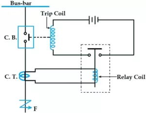
Relay circuit connections can be divide into three parts and that is :
- The first part is the primary winding of a current transformer which is connect in series with the line to be protect.
- The second part contains the secondary winding of the current transformer and the relay operating point.
- The third part is the tripping circuit consisting of the trip coil of the circuit breaker and the source of supply to the relay static contact.
When a short circuit occurs at point F on a transmission line, the current flowing in the line increases to a high value. This results in a heavy current flowing through the relay coil causing the relay to operate by closing its contacts.
This in turn closes the trip circuit of the breaker causing the circuit breaker to open and isolate the faulted section from the rest of the system. So in this way the relay circuit protects the equipment from damage and ensures normal functioning of the healthy part of the system.
What are the essential qualities of protective relaying?
The main function of protective relaying is to cause the immediate removal from service of any element of a power system when it start to operate in an abnormal manner or interferes with the effective operation of the rest of the system.
For a protective relay system to perform this function satisfactorily, it must have the following qualities.
- Selectivity
- Speed
- Sensitivity
- Reliability
- Simplicity
- Economy
See also this : What is fault in power system-Symmetrical and unsymmetrical fault
(1) selectivity :
It is the property by which only the faulty element of the system is isolated and the remaining healthy section are left intact in order to provide selectivity to the system it is necessary to divide the entire system into several protection zones.
When a fault occurs in a given zone then only the circuit breakers within that zone will be open. This system can be divide into the following.
- Generator
- Low voltage switch gear protection
- Power transformer protection
- Transmission line protection
- High voltage switch gear protection
(2) speed :
Protective relays are require to be quick acting due to the following reason :
- Critical clearing time should not be accident.
- Electrical equipment can be damage if they are make to carry fault current for long periods of time.
- High speed relay systems reduce the likelihood of one type of fault developing into another, more serious type.
(3) sensitivity :
It is the ability of a relay system to operate with a low value of active quantity.
The sensitivity of a relay is a function of the volt ampere input to the relay’s coil required for its operation. The smaller the volt-ampere input required for relay operation, the more sensitive the relay is. Thus 1 VA relay is more sensitive than 3 VA relay. It is desirable that the relay system be sensitive so that it operates with low values of volt-ampere input.
(4) reliability :
It can be expressed as a probability of failure therefore every component and circuit involve in fault clearance must be regarded as a potential source of failure. It can be reduce by proper reliable design.
(5) simplicity :
The relaying system should be simple so that it can be easily maintain. Reliability is closely related to simplicity. The simpler the protection scheme, the higher its reliability.
(6) Economy :
The most important factor in choosing a particular protection plan is the economic aspect. Sometimes it is economically unjustified to use an ideal scheme of protection and a compromise method has to be adopt.
As a rule, the cost of protective gear should not exceed 5% of the total cost. However, when the equipment to be protect is of extreme importance ( such as generator, main transmission line etc.) economic consideration are often subordinate to reliability.
See also this : Instruments and measurements – Classification of measuring instruments
What is a basic relay?
Most relays used in power systems operate on the basis of current and voltage supplied by current and voltage transformers which are connect in various combinations to the system element that is to be protect.
Through individual or relative changes in these two quantities, faults signal their presence, type and location to the protective relay. After detecting the fault, the relay operates the trip circuit resulting in opening of the circuit breaker and hence disconnection of the faulty circuit.
Most relays in service on electrical power systems today are of the electro mechanical type. They work on the following two main operating principles :
(a) Electromagnetic attraction and (b) Electromagnetic induction
(a) Electromagnetic attraction relays
Electromagnet attraction relays operate on the basis of an armature being attract to the poles of an electromagnet or a plunger being draw into a solenoid. This type of relay d. c. or a. c. can be implemented by quantity. The important types of electromagnetic attraction relays are :
- Attracted armature type relay
- Solenoid type relay
- Balanced beam type relay
1. Attracted armature type relay :

In the above diagram you can see the attracted armature type relay. It consists of a laminated electromagnet ‘M’ with a coil ‘C’ and a pivoted laminated armature. The armature is balanced by a counterweight and has a pair of spring contact fingers at its free end.
Under normal operating conditions the current through the relay coil ‘C’ is such that the counterweight holds the armature at the position shown. However, when a short circuit occurs, the current through the relay coil increases sufficiently and the relay armature is attract upwards.
This trip completes the circuit resulting in opening of the circuit breaker and hence disconnection of the faulty circuit. The minimum current at which the relay armature is attracted to close the trip circuit is called pickup current.
2. Solenoid type relay :

It consists of a solenoid and movable iron plunger under normal operating condition the current through the relay coil is such that it holds the plunger by gravity or spring in the normal position when a fault occurs the current through the relay coils becomes more than the pickup value. You can see the solenoid type relay in the above figure.
Causing the plunger to be attract to the solenoid the upward movement of the plunger closes the trip circuit and thus opening the circuit breaker and disconnect the faulty circuit.
3. Balanced beam relay :

In the above picture you can see the balanced beam rally. It consists of an iron armature attached to a balance beam. Under normal operating conditions the current through the relay coil is such that the beam is held in a horizontal position by a spring.
When a fault occurs the current through the relay coil exceeds the pickup value and the beam is attract to close the trip circuit. whose result is opening of circuit breaker contact and isolates the faulty part from the circuit.
See also this : What is electrical short circuit-Definition, Effects.
(b) Electromagnetic induction relay
This relay operate on the principle of induction motor and used for protective relaying purposes involving a. c. quantities only. Because of their principle of operation they are not use with d. c. quantities.
An induction relay essentially consists of a pivoted aluminum disc placed in two alternating magnetic fields of the same frequency but displaced in time and space. Torque is produced by the interaction of one magnetic field in the disc with the currents induced in the disc by the other.
To understand the generation of torque in an induction relay, refer to the elementary arrangement shown in figure-1.

Φ1 = Φ1max sin ωt
Φ2 = Φ2 max sin (ωt + α)
So here, i1 ∝ dΦ1 / dt ∝ Φ1max cos ωt
and i2 ∝ dΦ2 / dt ∝ Φ2max cos (ωt + α)
Now, F1 = Φ1 i2
F2 = Φ2 i1
Net force , F = F2 − F1
F = Φ2 i1 − Φ1 i2
= Φ2max sin (ωt + α) Φ1max cos ωt − Φ1max sin ωt Φ2max cos (ωt + α)
Now we take common
So, = Φ1max Φ2max [ sin (ωt + α) cos ωt − sin ωt cos (ωt + α)]
= Φ1max Φ2max sin α
= Φ1 Φ2 sin α
Two A. C. fluxes which are Φ2 and Φ1 which differ in phase by an angle α induce emf in the disc and cause the circulation of eddy currents i2 and i1 respectively. These currents lag behind their respective fluxes by 90°.
Referring to figure-2 where for the sake of clarity two A. C. flux and induced currents are shown separately.
Here the flux Φ1 and Φ2 are the rms value of fluxes the greater than the phase angle α between the fluxes the greater is the net force applied to the disc. maximum force will be produce when the two fluxes are 90° out of phase with each other.
There are three types of induction relay
- Shaded pole structure
- Watthour meter structure or double winding structure
- Induction cup structure
1. What is shaded pole structure?

So in the above picture you can see the shaded pole structure. It consists of an iron armature attached to a balance beam. Under normal operating conditions the current through the relay coil is such that the beam is held in a horizontal position by a spring. It consists of an aluminum disc pivoting freely to rotate in the air gap of the electromagnet. One half of each pole of the magnet is surround by a copper strip know as shading ring.
The alternating flux Φs in the shaded portion of the poles lag behind the flux Φu in the unshaded portion by an angle α. These two a. c. fluxes differing in phase will produce the necessary torque to rotate the disc.
Therefore the driving torque is given by T = Φs Φu sin α. Assume the fluxes Φs Φu are proportional to alternating current ‘I’ therefore torque = I2 sin α.
2. Watt hour meter structure

You can see the general arrangement of watt hour meter structure relay in the above figure. It consists of a pivoting aluminum disc arranged to rotate freely between the poles of two electromagnets. The upper electromagnet consists of two windings the primary and secondary.
The primary winding carries the relay current I1 while the secondary winding is connect to the winding of the lower magnet. The primary current induces an emf in the secondary and therefore a current I2 circulates in it.
The flux Φ2 induced in the lower magnet by the current in the secondary winding of the upper magnet will lag behind Φ1 by an angle α.
The two fluxes Φ1 and Φ2 differing in phase by α will produce a driving torque on the disc proportional to Φ1 Φ2 sin α. In this type of relay operation can be controlled by opening or closing the secondary winding circuit.
If this circuit is opened no flux can be set by the lower magnet but there will be current in the primary winding and hence no torque will be produce. So the relay can be make inoperative by opening the secondary winding circuit.
See also this : Explain UJT relaxation oscillator
3. What is induction cup structure?

So here in the above picture we can see the induction cup structure relay. Induction cup structure are more efficient torque producers then either the shaded pole or the watthour meter structure. Therefore this type of relay has very high speed and an operating time less than 1 second.
Here rotor iron is stationary only rotor conductor part is free to rotate. The rotating field is produced by two pairs of coils wrapped around on 4 poles, as shown.
The rotating field induces currents in the cup to provide the necessary driving torque. If Φ1 and Φ2 are the fluxes produced by the respective pair of poles then the torque produced is proportional to Φ1 Φ2 sin α. Where α is the phase difference between two fluxes.
Relay timing
1. Instantaneous relay
In this type of relay there is no intentional time delay is provided. In this case the relay contacts are close immediately after the current in the relay coil exceeds the minimum calibrated value. So the instantaneous relay we can see in the picture given below.

Its operating time is less than 0.1 second. This relay is effective only where the impedance between the relay and the source is small compared to the protected section impedance. And also in short transmission line.
The operating time also can be express in cycle based on the power system frequency. If the frequency is 50Hz than 1 cycle would be 1/50sec.
2. Inverse – time relay
Here the operating time is inversely proportional to the magnitude of actuating quantity. The relay never operates at a value of current less than the pickup. At higher values the operation time of the relay decreases continuously with increase in current.

This can be achieve by using mechanical accessories with relays. and Inverse time delay can be introduce using oil dashpot or time limit fuse.
The piston shows its upward motion on the oil dashpot connected to the moving plunger. At a current value equal to the pickup the plunger moves slowly and the time delay is maximum. At higher values of relay current the delay time is reduce due to greater pull on the plunger.

3. Definite time lag relay
In this type of relay a certain time elapse between the instant of pickup and the closing of the relay contacts. This particular time setting is independent of the amount of current through the relay coil.
This is the same for all value of current greater than the pickup value. So this type of relays is used in combination with inverse time relay.