
Speed control of DC motor :
The DC motor speed controller controls the speed of any common DC motor rated up to 100V. It operates on 5V to 15V.
The speed of a DC motor is given by the relation,
Where, N = speed of the motor
V = voltage across the armature
Ia = current through the armature
Ra = armature circuit resistance
K = constant
Φ = flux
From the above equation, it is clear that there are two main methods of controlling the speed of a DC motor, that is :
- By varying the flux per pole (Φ). This is known as flux control method.
- By varying the resistance in the armature circuit. This is known as armature control method.
The speed of a DC motor can also be controlled by changing the supply voltage V (voltage control method). Variation of the supply voltage is usually not possible unless the motor field is excited separately. Otherwise, variation of the supply voltage will also affect the field current and flux, making this method ineffective.
These methods applicable to shunt, series and compound motors will be discuss below.
See also this : What is DC motor? – Principle, Working, Types, Back emf, Significance
Speed control of DC shunt motor
The speed of a shunt motor can be varied by (1) flux control method and (2) armature control method. The first method is frequently used because it is simple and cheap.
Flux control method
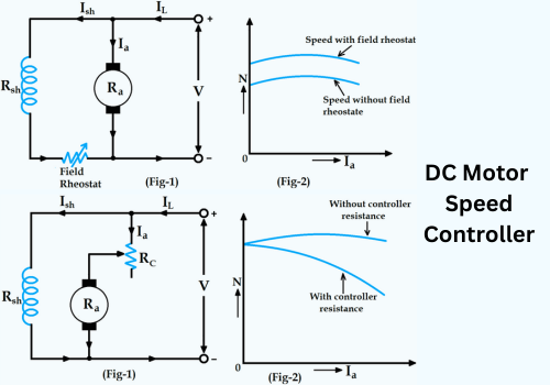
In this method, a variable resistance (which is known as shunt field rheostat) is placed in series with the shunt field winding as you can see in figure-1 below.
It is based on the fact that by varying the flux Φ, the motor speed (N ∝ I/Φ) can be changed and hence the name flux control method.
The shunt field rheostat reduces the shunt field current Ish and hence the flux Φ. So, we can only raise the speed of the motor above the normal speed (see in figure-2 below).

Usually, this method allows a speed increase in the ratio of 3 : 1. The wider speed range produces instability and poor commutation.
Advantages
- This is an easy and convenient method.
- This is a cheap method as very little power is wasted in the shunt field rheostat due to the relatively small value of Ish.
- The speed control used by this method is independent of the load on the machine.
Disadvantage
- Only higher than normal speeds can be achieve because the total field circuit resistance cannot be reduce by Rsh – shunt field winding resistance.
- There is a limit to the maximum speed that can be achieved by this method, this is because if the flux gets too much weak, commutation becomes poorer.
See also this : What are the characteristics of DC motor? – Shunt Motor, Series Motor, Compound Motor
Armature control method
This method is based on the fact that by varying the voltage available across the armature, the back emf and hence the speed of the motor can be changed.
This is done by inserting a variable resistance RC (which is known as controller resistance) in series with the armature (see in figure-1 below). Due to the voltage drop across the controller resistance, the back emf (Eb ) decreased. Because N ∝ Eb the speed of the motor decreases.
The highest speed obtainable is that corresponding to RC = 0, i.e. normal speed. Therefore, this method can only give a lower than normal speed (see fig-2 below).

Disadvantages
- A large amount of power is wasted in the controller resistance because it carries full armature current Ia.
- The output and efficiency of the motor decreases.
- This method results in poor speed regulation.
Due to the above disadvantages, this method is rarely use to control the speed of shunt motors.
The armature control method is a very common method for speed control of DC series motors. The disadvantage of poor speed regulation is not important in a series motor that is used only where varying speed service is required.
See also this : What is the DC generator? : Construction, Working principle, Types, EMF equation, Losses
Voltage control method
Speed control of DC motors can also be achieved by varying the applied voltage to the armature. The Ward-Leonard System of speed control is based on this principle.
In this system M (motor) is the main DC motor whose speed is to be controlled, and G (generator ) is a separately excited DC generator.
The generator G is driven by a 3-phase driving motor which can be an induction or synchronous motor. The combination of an AC driving motor and a DC generator is called a motor-generator (M-G) set.
Speed control of DC series motor
Flux control method
In this method, the flux produced by the series motor varies and hence the speed. The variation of flux can be obtained in the following ways :
See also this : What are the characteristics of DC generator?
1. Field diverters
In this method, a variable resistance (called field diverter) is connected in parallel with the series field winding as you can see in fig-1 below.
The effect is to shunt some portion of the line current from the series field winding, thus weakening the field and increasing the speed (because N ∝ 1/Φ).
The lowest speed achievable corresponds to zero current in the diverter (that is, diverter is open). The lowest speed that can be achieved is the normal speed of the motor.
As a result, this method can only provide speeds above normal speed. The series field diverter method is often employed in traction work.
2. Armature diverter
To obtain a speed below normal speed, a variable resistance (which is called armature diverter) is connected in parallel with the armature as you can see in fig-2 below.
The diverter shunts some of the line current, thus reducing the armature current. Now for a given load, if Ia is decreased, the flux Φ should increase (because T ∝ Φ Ia). Since N ∝ 1/Φ, the speed of the motor decreases. By adjusting the armature diverter, any speed lower than normal speed can be achieved.
See also this : What are the applications of DC generator?
3. Tapped field control
In this method, the flux is reduce (and hence the speed is increase) by reducing the number of turns of the series field winding as you can see in fig-3 below.
Switch S can short circuit any part of the field winding, thus reducing the flux and increasing the speed. With full turns of the field winding, the motor runs at normal speed and as the field turns on, higher than normal speed is achieved.

Armature-resistance control
As you can see in the figure below, a variable resistance is directly connected in series with the supply to the complete motor circuit.

This reduces the voltage available across the armature and hence the speed drops. Any speed below normal speed can be obtained by changing the value of the variable resistance.
This is the most common method for controlling the speed of DC series motors. Although this method has poor speed regulation, this is of no importance for series motors as they are used in varying speed applications.
For many applications of series motors the loss of power in series resistance is not very serious. Because in these applications, the control is not use for a large portion of the time for reduce speed under light-load conditions. And used only when the motor is carrying full-load.
Hope this information (speed control of DC motor) will help you. Thank you
See also this : What is torque in DC motor? – Define armature torque and shaft torque of DC motor