
There are two types of generators, one is DC generator and other is AC generator. So here we will discuss about the DC generator Construction, Working principle, Types, EMF equation, Losses. So let’s understand in detail.
Principle of a generator
An electrical generator is a machine which converts mechanical energy (or power) into electrical energy (or power).
It works on the following principle :
Whenever flux is cut through a conductor, an e.m.f. is induced which will cause current to flow when the conductor circuit is closed. The direction of induced e.m.f. is given by Fleming’s right hand rule. Therefore, the essential components of a generator are :
- a magnetic field
- conductor or a group of conductors
- motion of conductor w.r.t. magnetic field.
What is the DC generator?
An electrical generator is a machine in which mechanical energy is converted into electrical energy, it is called a DC generator. It is a rotating machine. DC generator also known as dynamo.
DC generator works on the principle of electromagnetic induction i.e. whenever a conductor cuts magnetic flux, dynamically induced emf is produced in it according to Faraday’s law of electromagnetic induction. The emf induced in the armature coil is proportional to the rate of change of flux linkage.
As an energy converter, the DC generator is not 100 percent efficient because there are energy losses in the machine.
See also this : Induction motor – Why motor is called induction?
What is the construction of a DC generator?
The general construction of DC generators and DC motors is the same. In fact, when the machine is being assembled, the workers usually do not know whether it is a DC generator or motor. Any DC generator can be run as a DC motor and vice-versa.
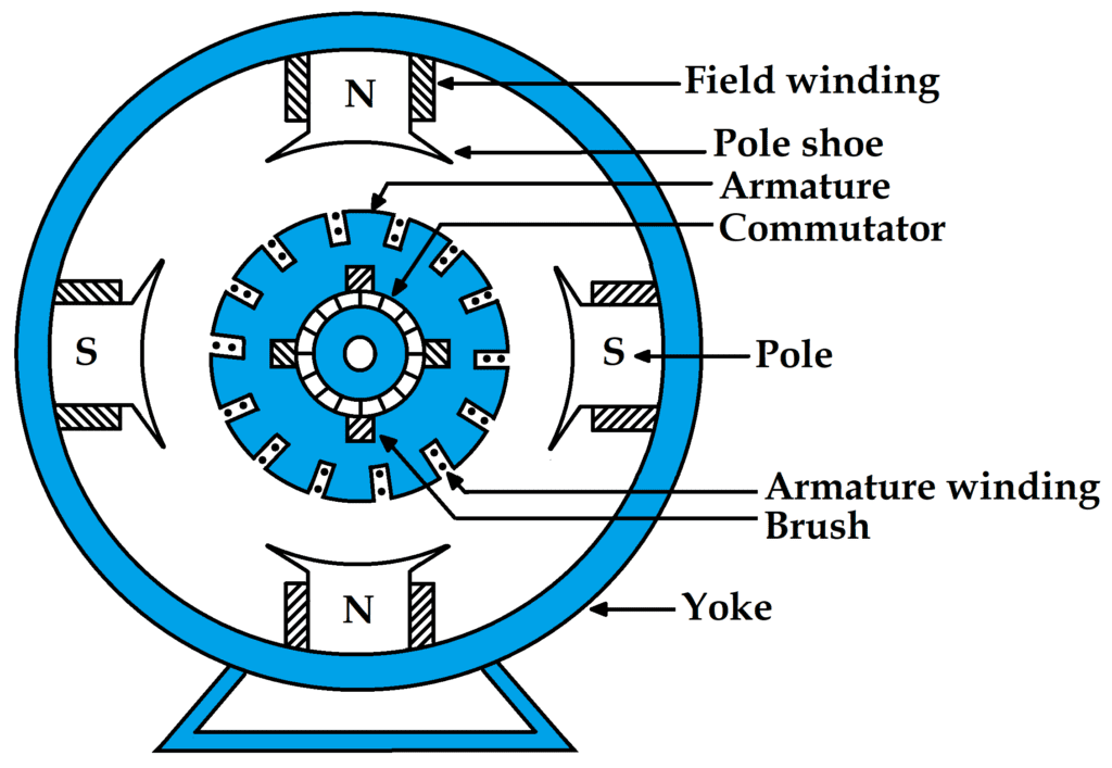
The above figure shows the sectional view of a four pole DC machine. A DC machine consists of two main parts :
- Stationary part : It designed mainly for producing magnetic flux.
- Rotating part : It is also called armature, where mechanical energy is converted into electrical (electric generator) or, conversely, electrical energy into mechanical (electric motor).
The basic constructional parts of DC machine are as below :
1. Yoke
The magnetic frame or yoke serves double purpose :
- It provides mechanical support for the poles and acts as a protecting cover for the entire machine.
- It carries the magnetic flux generated by the poles.
In small generators where cheapness rather than weight is the main consideration, yokes are made of cast iron. But for large machine usually cast steel or rolled steel is used.
It provides mechanical strength to the entire assembly and also carries the magnetic flux generated by the field winding.
2. Pole core and pole shoes
The field magnets consist of pole cores and pole shoes. Pole shoes serve two purposes
- They spread out the flux in the air gap and also, being of larger cross section, reduce the reluctance of the magnetic path.
- They support the exciting coil or field coil.
The pole core are made of laminated cast steel material. The pole core are bolted in the inner side of the yoke. The field windings are wound over pole core.
The pole shoes which are made of laminated cast steel material occupy maximum circumstances such that the fluxes uniformly distributed between armature conductor. Poles are laminated to reduce Eddy current loss.
3. Field system
The function of the field system is to generate a uniform magnetic field within which the armature rotates. It consists of a number of salient poles (of course, even number), which are bolted to the inside of a circular frame (usually called yoke).
The yoke is usually made of solid cast steel while the pole pieces are made of stacked laminations. So the field coils are mounted on the poles and carry DC exciting current. The field coils are connected in such a way that adjacent poles have opposite polarity.
4. Armature core
The armature core is coupled to the machine shaft and rotates between the field poles. It consists of slotted soft-iron laminations (about 0.4 to 0.6 mm thick) that are stacked to form a cylindrical core.
The laminations are individually coated with a thin insulating film so that they do not come into electrical contact with each other. So the purpose of laminating the core is to reduce eddy current losses.
The laminations are slotted to accommodate and provide mechanical security to the armature winding and to give shorter air gap for the flux to cross between the pole face and the armature “teeth”.
5. Armature winding
The slots of the armature core hold the insulated conductors which are connected in a suitable manner. This is known as armature winding.
It is the winding in which the “working” e.m.f. is induced.
The armature conductors are connected in series-parallel; the conductors being connected in series so as to increase the voltage and in parallel paths so as to increase the current.
The armature winding of a DC machine is a closed-circuit winding in which the conductors are connected in a symmetrical manner to form a closed loop or a series of closed loops.
6. Commutator
A commutator is a mechanical rectifier that converts the alternating voltage generated in the armature winding to direct voltage across the brushes.
The commutator is made of copper segments insulated from each other by mica sheets and mounted on the shaft of the machine. The armature conductors are suitably soldered to the commutator segments to give rise to the armature winding.
Depending on the way the armature conductors are connected to the commutator segments, there are two types of armature winding in a DC machine, they are
- Lap winding
- Wave winding
Great care is taken in manufacturing the commutator because any eccentricity will cause the brushes to jump, producing unacceptable sparking. The spark can burn the brushes and cause the commutator to overheat and carbonize.
7. Brushes
The propose of brushes is to ensure electrical connection between the rotating commutator and stationary external load circuit. So the brushes are made of carbon and are mounted on the commutator. Brush pressure is adjusted by means of adjustable springs.
If brush pressure is very large, friction produces heating of commutator and brushes. On the other hand, if it is too weak, incomplete contact with the commutator may produce sparking.
See also this : What is a 3 phase induction motor?
DC generator working principle
You must have heard about Faraday’s law of electromagnetic induction many times. So let us tell you that DC generator works on the basis of this Faraday’s law of electromagnetic induction.
Whenever flux cut by a conductor or a group of conductor an emf is induced according to Faraday’s law of electromagnetic induction and due to this induced emf a current is flow through the circuit if the whole circuit is closed. And the direction of the induced emf can be found out by Fleming right hand rule.
What are the types of armature winding?
There are two types of simple drum windings, and they are
- Simple lap winding
- Simple wave winding
Let us understand about them in detail.
What is simple lap winding?
In simple lap winding, the armature coils are connected in series through commutator segments in such a way that the armature winding is divided into as many parallel paths as the number of poles of the machine.
If Z is the conductor and P is pole, then P will be parallel paths, each with Z/ P conductors in series. Each parallel path will carry a current of Ia /P where Ia is the total armature current.
To sum up, in a simple lap winding :
- There are as many parallel paths as the number of poles (P) of the machine.
- Each parallel path has Z/P conductors in series where Z and P are the total number of armature conductors and poles respectively.
- e.m.f. generated = e.m.f. /parallel path.
- Total armature current, Ia = P × current/parallel path
What is simple wave winding?
In simple wave winding, the armature coils are connected in series through commutator segments in such a way that the armature winding is divided into two parallel paths irrespective of the number of poles of the machine.
If Z are the armature conductors, then Z/2 conductors will be in series in each parallel path. Each parallel path will have a current Ia /2 where Ia is the total armature current.
To sum up, in a simple wave winding :
- There are two parallel paths irrespective of number of poles of the machine.
- Each parallel path has Z/2 conductors in series, Z being total number of armature conductors.
- e.m.f. generated = e.m.f. /parallel path
- Total armature current, Ia = 2 × current/parallel path
What is the emf equation of DC generator?
Now we will derive an expression for the e.m.f. generated in the DC generator.
Let, Φ = flux/pole in weber
Z = total number of armature conductors
P = number of generator poles
A = number of parallel paths in armature
N = speed of armature in r.p.m. (revolutions per minute)
Eg = generated emf
Flux cut by one conductor in one revolution of the armature is
dΦ = P Φ weber
Time taken to complete one revolution is
dt = 60/N second
e.m.f. generated/conductor =
e.m.f. of generated, Eg = e.m.f. per parallel path
= (e.m.f. / conductor) × number of conductors in series per parallel path
Eg
Eg
Remember : For lap winding A = P and for wave winding A = 2.
For lap winding :
Number of parallel path = P
Number of conductors (in series) in one path = Z/P
Therefore, E.M.F. generated/path
For wave winding :
Number of parallel path = 2
Number of conductors (in series) in one path = Z/2
Therefore, E.M.F. generated/path
What is armature resistance (Ra)
The resistance offered by the armature circuit is known as armature resistance (Ra) and consist of :
- resistance of armature winding
- resistance of brushes
The armature resistance depends on the construction of the machine. Except in small machines its value is usually less than 1 Ω.
What are the different types of dc generators
The magnetic field in a DC generator is normally produce by electromagnets rather than permanent magnets. Generators are generally classified according to their methods of field excitation.
On this basis DC generators are divide into the following two classes :
- Separately excited DC generators
- Self-excited DC generators
The behaviour of a DC generator at load depends on the method of field excitation adopted.
What is separately excited DC generator?
A DC generator whose field magnet winding is supplied from an independent external DC source (such as a battery etc.) is called a separately excited generator.
The voltage output depends on the speed of rotation of armature and the field current (Eg = PΦZN / 60A). So the higher the speed and field current, the higher the generated e.m.f. It may be note that separately excited DC generators are rarely use in practice. DC generators are normally of self-excited type.

Armature current, Ia = IL
Terminal Voltage, V = Eg − IaRa
Electric power developed = EgIa
Power delivered to load = EgIa − I2aRa = Ia (Eg − IaRa ) = VIa
What is self excited DC generator?
A DC generator whose field magnet winding is supplied current from the output of the generator itself is called a self-excited generator.
There is always some flux present in the pole due to residual magnetism. When the armature is rotated, some e.m.f. and hence some induced current is produced which is partly or fully passed through the field coils thereby strengthening the residual pole flux.
So there are three types of self-excited generators named according to the manner in which their field coils (or windings) are connected to the armature.
- Series generator
- Shunt generator
- Compound generator
What is series generator?
In a series-wound generator, the field winding is connected in series with armature winding so that the entire armature current flows through the field winding as well as the load.
Since the field winding carries the entire load current, it consists of a few turns of thick wire of low resistance. Series generators are rarely used except for special purposes, for example as boosters.
Armature current, Ia = Ise = IL = I (say)
Terminal voltage, V = Eg − I (Ra +Rse)
Power developed in armature = Eg Ia
Power delivered to load = Eg Ia − I2a (Ra + Rse )
= Ia [Eg − Ia (Ra + Rse )]
= VIa or VIL
What is shunt generator?
In a shunt generator, the field winding is connected in parallel with the armature winding so that terminal voltage of the generator is applied across it.
The shunt winding consists of many turns of fine wire having high resistance. Therefore, only a part of armature current flows through shunt field winding and the rest flows through the load.
Shunt field current, Ish = V/ Rsh
Armature current, Ia = IL + Ish
Terminal voltage, V = Eg − Ia Ra
Power developed in armature = Eg Ia
Power delivered to load = VIL
What is compound generator?
In a compound-wound generator, there are two sets of field windings on each pole-one in series and the other in parallel with the armature.
It is a combination of few series and a few shunt windings. In a compound generator the shunt field is stronger than the series field. When series field assists the shunt field, the generator is said to be commutatively-compound. On the other hand if series field opposes the shunt field, the generator is said to be differentially compounded.
So there are two types of compound wound generators, they are —
- Short shunt
- Long shunt
What is long and short shunt?
Short shunt – If the shunt field winding is connected in parallel with armature only then these known as short shunt (see figure-1).
Series field current, Ise = IL
Shunt field current, Ish = (V + Ise Rse) / Rsh
Terminal voltage, V = Eg − Ia Ra − Ise Rse
Power developed in armature = Eg Ia
Power delivered to load = VIL

Long shunt – If the shunt field winding is connected in parallel both armature and series field winding then it is known as long shunt. (see figure-2)
Series field current, Ise = Ia = IL + Ish
Shunt field current, Ish = V / Rsh
Terminal voltage, V = Eg − Ia (Ra + Rse )
Power developed in armature = Eg Ia
Power delivered to load = VIL
Losses in a DC machine

The losses in a DC machine (generator or motor) can be divide into three classes
- Copper losses
- Iron or core losses
- Mechanical losses.
All these losses appear as heat and thus increase the temperature of the machine. They also reduce the efficiency of the machine.
Copper losses
These losses are due to the current in the different windings of the machine.
- Armature copper loss = I2a Ra
- Shunt field copper loss = I2sh Rsh
- Series field copper loss = I2se Rse
There is also brush contact loss due to brush contact resistance (that is resistance between the surface of brush and surface of commutator). So these losses are usually included in armature copper loss.
Iron or Core losses
This losses occur in the armature of a DC machine and are due to the rotation of armature in the magnetic field of the poles. This losses also known as magnetic losses. So they are of two types
- Hysteresis loss
- Eddy current loss
Hysteresis loss
Hysteresis losses occur in the armature of a DC machine because any part of the armature is subject to magnetic reversal as it passes under successive poles. So it is given by ;
Hysteresis loss, Ph = η B1.6max f V watts
Where, Bmax = Maximum flux density in armature in Wb / m2
f = Frequency of magnetic reversals
= NP / 120 where N is in r.p.m.
V = Volume of armature in m3
η = Steinmetz hysteresis coefficient
To reduce this loss in a DC machine, armature core is made of materials that have a low value of Steinmetz hysteresis coefficient for example silicon steel.
Eddy current loss
When armature rotates in the magnetic field of the poles, an e.m.f. is induced in it which circulates eddy currents in the armature core. The power loss due to these eddy currents is called eddy current loss.
To reduce this loss, the armature core is built up of thin laminations insulated from each other by a thin layer of varnish.
Eddy current loss , Pe = Ke B2max f2 t2 V watts
Where , Ke = Constant
Bmax = Maximum flux density in the core in Wb / m2
f = Frequency of magnetic reversals in Hz
t = Thickness of lamination in m
V = Volume of core in m3
Eddy current loss depends on the square of thickness of the lamination. For this reason the thickness of the lamination should be kept as low as possible.
Mechanical losses
These losses are caused by friction and windage.
- Friction loss for example, bearing friction, brush friction etc.
- windage loss that is air friction of rotating armature.
So these losses depend on the speed of the machine. But for a given speed, they are practically constant.
What is stray losses? : Usually, magnetic and mechanical losses are collectively known as stary losses.
What are constant and variable losses
The losses in a DC generator (or DC motor) can be subdivided into
- constant losses
- variable losses
Constant losses
Those losses in a DC generator which remain constant at all loads are known as constant losses. So the constant losses in a DC generator are :
- Iron losses
- Mechanical losses
- Shunt field losses
Variable losses
In a DC generator those losses which vary with load are called variable losses. So the variable losses in a DC generator are
- Copper loss in armature winding (I2a Ra )
- Copper loss in series field winding (I2se Rse )
Remember : Total losses = Constant losses + Variable losses
Power stages of DC generator
In case of DC generator the various power stage are show below.
A – B = Iron and friction losses
B – C = Copper losses

- Mechanical efficiency – ηm = B/A = Eg Ia / Mechanical power input
- Electrical efficiency – ηe = C/B = VIL / Eg Ia
- Commercial or overall efficiency – ηc = C/A = VIL /Mechanical power input
It is clear that the overall efficiency, ηc = ηm × ηe.
Now, commercial efficiency, ηc = C/A = output / input =
Condition for maximum efficiency of DC generator
The efficiency of a DC generator is not constant but varies with the load. Consider a shunt generator delivering load current IL at terminal voltage V.
Generator output = VIL
Generator input = Output + Losses
= VIL + Variable losses + Constant losses
= VIL + I2a Ra + Wc
So, = VIL + ( IL + Ish )2 Ra + Wc (Because Ia = IL + Ish)
The shunt field current Ish is generally small compared to IL and hence can be neglected.
Therefore, Generator input = VIL + I2L Ra + Wc
η = output / input = VIL /(VIL + I2L Ra + Wc )
=
Now, efficiency is maximum when denominator is minimum i.e. when
I2L Ra = Wc
I2L Ra is the variable loss and Wc is the constant loss.
So the load current corresponding to maximum efficiency is given by
I2L Ra = Wc
Therefore, the efficiency of a DC generator will be maximum when the load current is such that variable loss is equal to the constant loss.
What is armature reaction?
We have considered that the only current acting in a DC machine is due to the main poles called main flux.
The current flowing through the armature conductors also creates a magnetic flux (called armature flux) which distorts and weakens the flux coming from the poles.
This distortion and weakening of the field occurs in both the generators and motors. The action of armature flux on the main flux is known as armature reaction.
The phenomenon of armature reaction in a DC generator see the figure below. Only one pole is show for clarity.

When the generator is at no-load, a small current flowing in the armature does not appreciably affect the main flux Φ1 coming from the pole (See Fig-1).
When the generator is loaded, current flowing through the armature conductors sets the flux Φ2. In Fig-2 shows the flux due to armature current alone. By superimposing Φ1 and Φ2, so we get the resulting flux Φ3 (See figure-3).
Referring to Fig-3, it is clear that flux density at the trailing pole tip (point B) is increase while at the leading pole tip (point A), it is decrease.
This unequal field distribution produces the following two effects :
- The main flux is distorted.
- Due to the high flux density at pole tip B, saturation sets in. As a result, the increase in flux at pole tip B is less than the decrease in flux under pole tip A. Flux Φ3 is at full load, therefore, flux Φ1 is less than at no-load.
What is the problem of armature reaction in DC generator?
In a DC machine the armature reaction distorts and weakens the main flux. This invites the following two problems :
- Armature reaction can reduce the main flux by up to 10%. So this causes the generated e.m.f. in a generator to fall with the increase in load current.
- To ensure good commutation, the brushes must be placed in neutral zone. Due to the distortion of flux, the neutral zone is shifted. If the load changes frequently, it is not practical to change the position of the brushes.
What is commutation in generator?
There are two parallel paths between the brushes. Therefore, each coil of the winding carries half (i.e. Ia /2 in this case) of the total current (Ia) entering or leaving the armature circuit.
The currents in the coils connected to the brush are either all towards the brush (positive brush) or all directed away from the brush (negative brush). Therefore, the current in the coil will be reversed as the coil passes through a brush. This reversal of current in the coil as the coil passes through a brush is called commutation.
The complete reversal of current in the coil at a uniform rate as the coil passes through the brushes is called ideal commutation.
When commutation occurs, the coil passing through the commutation is short-circuited by the brushes. For ideal commutation, the following assumptions are made :
- The insulation between commutator segments is of negligible thickness compare to the width of commutator.
- The resistance of the armature coil is negligible compare to the resistance of the carbon brush in contact with copper segment.
- The armature coil has negligible inductance.
See also this : What is alternator in electrical
What is the advantage and disadvantage of DC generator?
Advantages :
- The construction of DC generator is simple and its design is also simple.
- One of the advantages of DC generator is that using it a big machine can be run.
- DC generators are capable of supplying power to large motors.
- Power can also be supplied to heavy electrical equipment or devices using a DC generator.
- A DC generator greatly reduces the electric power fluctuations in the armature and gives a constant supply.
Disadvantages :
- DC generator cannot be use with transformer.
- DC generators are very less efficient.
- DC generator experiences many losses like eddy current loss, copper loss, mechanical loss, when the current flows in the dc generator.
- There can be a large voltage drop in the generator when this generator is placed over a long distance.
So I hope this information will help you, Thanks.