
Here I will discus with you about USART 5251 microprocessor, it is also know as programable communication interface intel 8251 and USART stands for Universal Synchronous/Asynchronous Receive/transmitter.
Programmable communication interface is use for serial data transmission, The I.C. chip is fabricated using N-channel silicon gate technology. The 8251 can be use to transmit or receive serial data.
It accepts data in parallel format from the microprocessor and converts them into serial data for transmission. It also receives serial data and converts them in parallel and sends the data in parallel format to the CPU.
You can see the details of some important pins below.
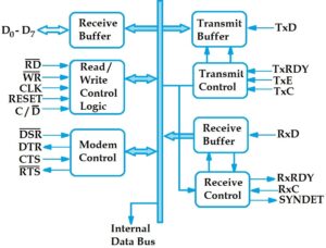
Block diagram of 8251
Check this also Block diagram of 8253
USART 8251 pin diagram

Pin description of 8251 USART
C / D : ( Control or data ) When it is low data is transmitted on the data bus and when it is high control signals are transmitted on the data bus.
RD : ( Read ) When it is low the CPU reads data from the intel 8251.
WR : ( Write ) When it is low the CPU writes the data to the intel 8251.
DSR : Data set ready
RTS : Request to send
CTS : ( Clear to send ) The low in this pin enables the 8251 to transmit serial data.
DTR : Data terminal ready
Check this also Flags in 8085 microprocessor
TxC : ( Transmitter clock ) It controls or allow the rate of data transmission.
TxE : ( Transmitter empty ) When it is goes high the 8251 has no characters to transmit.
TxRDY : Transmitter ready
RxRDY : Receiver ready
RxD : Line for receiving data
TxD : Line for serial data transmission
RxC : ( Receiver clock ) It control the rate at which characters are receive.
A high on the T×RDY line informs CPU that the transmitter is ready to accept data. and This line goes low when data is receive from CPU. On receiving the data byte the 8251 sends serial data on R×D line, when CTS is low and the transmitter is enable by CPU. The clock input on T×C controls the rate of serial data transmission.
Check this also 8085 pin diagram
Baud rate
In synchronous transmission mode, the baud rate is equal to the clock frequency. In asynchronous transmission mode the baud rate is a fraction of the clock frequency. So the fraction may be 1,( 1/16 ), ( 1/64 ).
Serial data are receive on the RxD line and RxRDY is normally low. When serial data is received up to the 8251, it goes high and informs the CPU that the 8251 contains data which are ready to be sent to the CPU.
DSR, DTR, RTS and CTS are standard modem control signals. These control lines are connect to the corresponding lines of the modem being use. Modem is a modulating / demodulating device. It adds the carrier frequency to the data transmission at the higher frequency receive from a higher frequency channel.
The 8251 sends a low DTR signal to the modem to indicate that it is ready to send data. By making DSR low the modem replies that it is also ready for onward transmission of data to be communication system.
When both the modem and USART are ready for data transmission the 8251 sends a low RTS signal to the modem to initiate data transmission.
The modem 8251 accepts this request by reducing CTS. A low CTS enables the 8251 transmission logic. If for any reason the data transmission has to be stopped, the CTS is made higher.
So friends, this was some important information about USART 8251 microprocessor we hope that you must have got to know a lot from this article. and share this information with your friends as much as possible, Thank you.