
Here today we are going to discuss about the working of JK flip-flop. And also we will look at the truth table. So stay with us till the end. So let’s start.
The JK flip-flop has two inputs J and K. It is the improved version of RS flip flop so that when both inputs 1 then also the output Q and ![]() are complement to each other.
are complement to each other.
See also this : Feedback in electronics
Working of JK flip flop
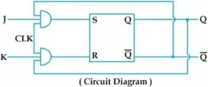
In this figure two AND gate are placed to the SR flip flop the input of first and AND gate are J, ![]() AND clock and the second input gate are K, Q AND clock. Clock signal is provided to both the AND gates for enable flip flop operation.
AND clock and the second input gate are K, Q AND clock. Clock signal is provided to both the AND gates for enable flip flop operation.
When J = 0 and K = 0 , the two AND gates are disable and the input to the SR flip flop will be 0. And the flip flop remains in its last value. When J = 0 and K = 1 the first AND gate is disable the second AND gate will enable when if Q = 1.
Now the output of two AND gates are 0 and 1. So it sends a reset signal to the SR flip flop. So the  = 0 , = 1 and it disable the second AND gate. When J = 1 and K = 0 the second AND gate are disable the first AND gate when enable when = 1. Now the input to the SR flip flop are 1 and 0. So its sends a SET signal to the flip flop. So the output Q = 1 and = 0 after this again first AND gate also disable because
 ![]() = 0.
= 0.
When J = 1 and K =1 both the AND gates can be enable which is possible to SET or RESET the flip flop. Suppose if Q is 1 then second AND gate enable and the SR flip flop is in RESET condition.
So the output is Q = 0 and = 1.
If Q = 0 and = 1 then it disable the second AND gate and enables the first AND gate. So the input to the SR flip flop is a SET condition. So the output will Q = 1 and = 0. When J = 1 and K = 1 the flip flop will be toggling and the compliment the output from its last output.
Truth table of JK flip flop
| J | K | QT+1 | State |
| 0 | 0 | Q | No change |
| 0 | 1 | 0 | Reset |
| 1 | 0 | 1 | Set |
| 1 | 0 | | Toggle |
See also this : Four bit ripple counter – What is 4-bit ripple counter?