
Here we are discuss some information about working of four bit ripple counter. So till the end stay with us and lets start. One more thing remember a 4-bit ripple counter is also know as 4-bit asynchronous/binary/ripple counter.
What is a counter ?
Flip flops can be connect together to perform counting operation and such a condition of flip flop is counter. A counter with ‘n’ number of flip flop can count maximum ‘2n‘ state.
So there are two types of counter (1) Asynchronous and (2) Synchronous counter.
See also this : Feedback in electronics
4 bit asynchronous ripple counter
The counter consists of four flipflops and it can count 16 states. The clock pulse is given to the first flipflop and the normal output of the first flipflop is considered as the clock input of second flipflop and so on.
The asynchronous counter is construct using T flipflops on JK flipflop with J = 1 and K = 1. Consider a JK flipflop, this flipflop changes state on the trailing edge of the clock pulse. We use four flipflops in a cascade to hold a 4 bit counter.
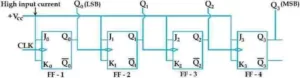
A square wave drives the first flipflop. The output of the Q0 flipflop Q0 drives Q1 flipflop and the Q1 flip in turn drives the flipflop which then drives the Q3 flipflop. All the inputs of JK flipflop are +Vcc tied to. Under these situation each flipflop changes its position when a negative edge clock pulse occurs.
Let us assume that all flipflops are initially reset to output 0. So output condition to start with will be Q3 Q2 Q1 Q0 = 0000, the above condition can be obtained by applying clear signal (CLR) on all the flipflops simultaneously.
Now on the arrival of the 1st clock pulse the flipflop Q0 changes position on occurrence of the negative edge of the clock pulse. Hence after the end of the first pulse the output condition will be Q3 Q2 Q1 Q0 = 0001.
The flipflops Q1 Q2 Q3 one unaffected.
When the second clock pulse comes on the back edge of the clock pulse Q0 flipflop again changes its earlier state that is it goes from 1 to 0. That is it is a negative changes.
This negative change occurs when fed to flipflop Q1 and forces it to change its output to 1 which was 0 before. The flipflop Q2 and Q3 remain unaffected.
See also this : What is rectifier in electronics
So the output condition Q3 Q2 Q1 Q0 = 0010.
When the third pulse comes on the arrival of the negative edge of the clock pulse, the state of the output of Q0 changes from 0 to 1. Since this change is positive so the rest of the flipflop are unaffected. So the output condition is Q3 Q2 Q1 Q0 = 0011.
Flipflop Q0 changes from 1 to 0 when the fourth clock pulse has a negative edge. Since this is a negative change, when it is fed into the clock signal of the Q1 flipflop, it forces the Q1 flipflop to change its output from 1 to 0.
Again this is a negative change. When this negative going pulse is fed to Q2 from the output of Q1 and it forces the flipflop Q2 to change its output from 0 to 1. Since this change is positive so the flipflop Q3 is unaffected. So the output condition is Q3 Q2 Q1 Q0 = 0100.
Similarly, after the arrival of the negative edge of the 5th pulse, the output condition of the flipflop changes as 0101 ad so on.
4 bit ripple counter timing diagram

See also this : Explain push pull amplifier
4-bit ripple counter truth table

In this counter negative edge figuring clocks pulse is use. The counting states are 0 to 15 and it resets to zero in the next clock pulse.
So friends this is some information about it 4-bit ripple counter. If you have any suggestion please comment us. Thank you