
Introduction of transistor tuned amplifier –
An audio amplifier amplifies a wide band of frequencies equally well and does not allow the selection of a particular desired frequency while rejecting all other frequencies.
Sometimes it is desired that an amplifier should be selective that is it should select desired frequency or narrow band of frequencies for amplification. For example, radio and television broadcasting is carried out on a specific radio frequency assigned to the broadcasting station.
Radio receivers are require to pick up and amplify desired radio frequency while discriminating against all others. To achieve this, the simple resistive load is replaced by a parallel tuned circuit whose impedance strongly depends on frequency.
Such a tuned circuit becomes very selective and very strongly amplifies resonant frequency and narrow band signals on both sides. Therefore, the use of tuned circuits in conjunction with a transistor makes possible the selection and efficient amplification of a particular desired radio frequency. Such an amplifier is called tuned amplifier.
See also this : What is transistor audio power amplifier?
What is tuned amplifiers?
Amplifiers that amplify a specific frequency or narrow band of frequencies are called tuned amplifiers.
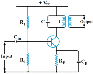
Tuned amplifiers are mostly use for amplification of high or radio frequencies. This is because radio frequencies are generally single and the tuned circuit allows their selection and efficient amplification. In the above figure you can see the circuit of a simple transistor tuned amplifier.
Such amplifiers are not suitable for amplification of audio frequencies as they are mixture of frequencies from 20 Hz to 20 kHz and not single. Tuned amplifiers are widely used in radio and television circuits where they are called upon to handle radio frequencies.
Here, we have a parallel tuned circuit in the collector. The impedance of this tuned circuit strongly depends on the frequency. It provides very high impedance at resonant frequency and very low impedance at all other frequencies.
If the frequency of signal is same as the resonant frequency of LC circuit, large amplification will result at this frequency due to the high impedance of LC circuit.
When signals of many frequencies are present at the input of tuned amplifier, it will select and amplify signals of the resonant frequency while rejecting all others.
Therefore, such amplifiers are very useful in radio receivers for selecting the signal from a particular broadcast station when signals of many other frequencies are present in the receiving aerial.
See also this : What is Single Stage Transistor Amplifier?
What are advantages and disadvantages of tuned amplifiers?
The advantages of tuned amplifier are.
- In tuned circuits use inductors and capacitors reactive components to reduce power losses, and make tuned amplifiers efficient.
- Due to its small resistance in a parallel tuned circuit a small collector will supply VCC.
- These amplifiers have good signal to noise ratio as compared to other amplifiers.
- In amplifiers tuned to amplify signals, the bandwidth factor is variable.
The disadvantages of tuned amplifier are.
- Due to the presence of inductors and capacitors in tuned circuits, the overall circuit is expensive as well as heavy.
- The amplification cannot be achieve in the audio frequency range.
- Complexity arises in the circuit due to increase in bandwidth
Tuned amplifier applications
- Tuned amplifiers employed for high or radio frequency (RF) amplification because it is generally require to amplify a single frequency rejecting all other frequencies. For this purpose, tuned amplifiers are use.
- These amplifiers use tuned circuits as the collector load and provide the desired selective property.
- This amplifier is use as intermediate frequency amplifier in super heterodyne receiver.
- Tuned amplifiers are use to amplify the desired signal to higher level and are use in wireless long-distance communication systems.
- A tuned amplifier uses LC tank load. This permits the amplifier to select a desired frequency or narrow band of frequencies for amplification.
- A tuned amplifier is use in radio frequency applications.
See also this : What is Multistage Transistor Amplifier?
Distinction between tuned amplifier and other amplifiers
Amplifiers (such as voltage amplifier, power amplifier etc.) provide constant gain over a limited band of frequencies, that is from lower cut-off frequency f1 to upper cut-off frequency f2. Now bandwidth of the amplifier, BW = f2 − f1.
Note this point what separates a tuned amplifier from other amplifiers? The difference is that tuned amplifiers are design for a specific, usually narrow bandwidth. This point you can see in figure-1.
The BWS is the bandwidth of standard frequency response while BWT is the bandwidth of the tuned amplifier. In many applications, the lower the bandwidth of a tuned amplifier, the better.

Example : Consider a tuned amplifier that is design to amplify only those frequencies that are within ± 20 kHz of the center frequency of 1000 kHz (that is fr = 1000 kHz ). See figure-2.
f1 = 980 kHz, fr = 1000 kHz, f2 = 1020 kHz, BW = 40 kHz
It means that as long as the input signal is within the range of 980–1020 kHz, it will be amplified. If the frequency of input signal falls outside this range, amplification will drop significantly.
What is parallel tuned circuit?
In a parallel tuned circuit capacitor C and inductor L are in parallel as you can see in Fig-1 which is below. If an alternating voltage is applied to this parallel circuit, the frequency of oscillations will be frequency of the applied voltage. However, if the frequency of applied voltage is equal to the natural or resonant frequency of LC circuit, electrical resonance will occur.
Under such conditions the impedance of the tuned circuit becomes maximum and the line current becomes minimum. The circuit then draws enough energy from AC supply as needed to overcome the losses in resistance R.
Parallel resonance
A parallel circuit containing reactive elements (L and C ) is resonant when circuit power factor is unity i.e. applied voltage and supply current are in phase. You can see the phasor diagram of parallel circuit in figure-2 which is below.
The coil current IL has two rectangular components namely active component IL cos ΦL and reactive component IL sin ΦL. This parallel circuit will be resonant when the circuit power factor is one. This is possible only when the net reactive component of the circuit current is zero
IC − IL sin ΦL = 0
IC = IL sin ΦL
Resonance can be achieve in a parallel circuit by changing the supply frequency. At some frequency, fr (called resonant frequency), IC = IL sin ΦL and resonance occurs.
Resonant frequency
Resonant frequency definition – The frequency at which parallel resonance occurs (that is reactive component of circuit current becomes zero) is called the resonant frequency fr.

At parallel resonance, we have IC = IL sin ΦL
Now, IL = V/ZL , sin ΦL = XL / ZL and IC = V/XC
Therefore, V / XC = ( V / ZL )×( XL / ZL )
XL XC = Z2L
ωL / ωC = Z2L = R2 + X2L ……..(eq-1)
L / C = R2 + ( 2 π fr L )2
( 2 π fr L )2 = ( L / C ) − R2
Therefore Resonant frequency, …….(eq-2)
If coil resistance R is small (as it usually is), then,
……..(eq-3)
The resonant frequency will be in Hz if R, L and C are in Ohm, Henry and Farad respectively.
Remember one thing – If the value of R is given in the question, then equation-2 should be used to find fr. And, if R is not given, then equation-3 can be used to find fr.
What is the frequency response of tuned amplifier?
The voltage gain β of the amplifier depends on the input impedance and effective collector load. In a tuned amplifier, tuned circuit is used in the collector.
Therefore, the voltage gain of such an amplifier is provide by
Voltage gain = β ZC / Zin
Where ZC = effective collector load
Zin = input impedance of the amplifier
The value of ZC and hence gain depends on the frequency in the tuned amplifier. Since ZC is maximum at resonant frequency, therefore, the voltage gain will be maximum at this frequency. ZC and gain decrease as the frequency varies above and below the resonant frequency.
As you can see the frequency response diagram of a tuned amplifier which is below. It is clear that voltage gain is maximum at resonant frequency and decreases as the frequency is varied in either direction from resonance.

Bandwidth
Bandwidth definition – The range of frequencies over which the voltage gain of a tuned amplifier drops to 70.7 % of the maximum gain is called its bandwidth.
With reference to above figure the bandwidth of tuned amplifier is f2 − f1. The amplifier will nicely amplify any signal in this frequency range. The bandwidth of tuned amplifier depends on the value of Q of LC circuit, that is, the sharpness of the frequency response.
The higher value of Q of tuned circuit, the lower the bandwidth of the amplifier and vice-versa. The value of Q of LC circuit is made in such a way as to allow amplification of the desired narrow band of high frequencies.
The practical importance of bandwidth of tuned amplifiers is found in communication system. In radio and TV broadcasting, a very high frequency wave, called carrier wave is used to carry the audio or picture signal. In radio broadcasting, the audio signal has a frequency range of 10 kHz.
The tuned amplifier should have a bandwidth of 705 kHz to 715 kHz (that is 10 kHz).
See also this : What are the different classification of power amplifiers?
What is the relationship between Q and bandwidth?
The quality factor Q of a tuned amplifier is equal to the ratio of resonant frequency (fr ) to bandwidth (BW) that is.
Q = fr / BW
The Q of the amplifier is determine by the circuit component values.
It may be noted here that Q of a tuned amplifier is generally greater than 10. When this condition is met, the resonant frequency at parallel resonance is approximately given by
fr = 1 / 2π √LC
Analysis of tuned amplifier
A Parallel LC circuit is present in the collector circuit of the transistor. When the circuit has high Q, the parallel resonance occurs at a frequency fr given by ;
fr = 1 / 2π √LC

Figure-1 show a single tuned amplifier. At resonant frequency, the impedance of a parallel resonant circuit is very high and is purely resistive. Therefore, when the circuit is tuned to the resonant frequency, the voltage across RL is maximum.
In other words, the voltage gain is maximum at fr. The voltage gain decrease sharply above and below the resonant frequency. The higher the Q of the circuit, the faster the gain decreases on either side of resonance (see figure-2).
A.C. Equivalent circuit of tuned amplifier
To fully understand the operation of this circuit, we will look at its behavior at three frequency conditions. In figure-1 you can see the AC equivalent circuit of the tuned amplifier.

- fin = fr
- fin < fr
- fin > fr
Let us understand these concepts.
1. When input frequency equals fr (i.e. fin = fr )
When the frequency of input signal is equal to fr, the parallel LC circuit provides a very high impedance that is it acts as an open. Since RL represents the only path to ground in the collector circuit, all AC collector current flows through RL. Hence, voltage across RL is maximum that is voltage gain is maximum ( see in Fig-2).
2. When input frequency is less than fr (i.e. fin < fr )
When input signal frequency is less than fr, the circuit is effectively inductive. As the frequency decreases from fr, a point is reached when XC − XL = RL. When this happens, the voltage gain of amplifier is reduced by 3dB.
In other words, the lower cut-off frequency f1 for the circuit occurs when XC − XL = RL.
3. When input frequency is greater than fr (i.e. fin > fr )
When the input signal frequency is greater than fr, the circuit is effectively capacitive. As fin is increased beyond fr, a point is reached when XC − XL = RL. When this happens, the voltage gain of amplifier will drop again by 3dB.
In other words, the upper cut-off frequency for the circuit will be when XC − XL = RL.
See also this : Explain push pull amplifier
What are the types of tuned amplifier?
Here we will understand about three types of tuned amplifiers which are
- Single tuned amplifier
- Double tuned amplifier
- Stagger tuned amplifiers
What is single tuned amplifier?
A single tuned amplifier consists of a transistor amplifier with a parallel tuned circuit as collector load. The values of capacitance and inductance of tuned circuit are chosen such that its resonant frequency is equal to the frequency to be amplified.
The output from a single tuned amplifier can be obtain either (a) by the coupling capacitor CC as you can see in Fig-1 or (b) by the secondary coil as you can see in Fig-2.

Operation
The high frequency signal to be amplified is fed to the input of the amplifier. The resonant frequency of parallel tuned circuit is made equal to the frequency of signal by changing the value of C.
Under such conditions, the tuned circuit will provide very high impedance to the signal frequency. Hence a large output appears in the tuned circuit.
If the input signal is complex containing many frequencies, only the frequency that corresponds to the resonant frequency of the tuned circuit will be amplified. All other frequencies will be rejected by the tuned circuit. In this way, a tuned amplifier selects and amplifies the desired frequency.
Advantages of single tuned amplifier
- The desired frequencies can be select using this amplifier.
- The selectivity of this amplifier is high.
- Due to the lack of Rc, the collector voltage supply in this amplifier is low.
- In this amplifier power loss is low due to the lack of collector resistance.
Disadvantages of single tuned amplifier
- In a single tuned amplifier, the product of the gain bandwidth is small.
- In this amplifier its potential instability will arise due to the lack of bandwidth.
Application of single tuned amplifier
- This amplifier is use in television and radio. And it is also use in the primary internal stage of a radio receiver where the front end can be select using an RF amplifier.
- This amplifiers are use in the amplification of video signals.
What is double tuned amplifier
It consists of a transistor amplifier consisting of two tuned circuits, one (L1 C1 ) in the collector and the other (L2 C2 ) in the output. The high frequency signal to be amplified is applied to the input terminals of the amplifier. You can see the circuit of a double tuned amplifier which is below.
The resonant frequency of the tuned circuit L1 C1 is make equal to the signal frequency. Under such conditions, the tuned circuit provides very high impedance to the signal frequency. As a result, large output appears in the tuned circuit L1 C1.
The output from this tuned circuit is transfer to another tuned circuit L2 C2 by mutual induction. Double tuned circuits are widely used to connect various circuits of radio and television receivers.

Advantages of double tuned amplifier
- Its main advantages are that it is an amplifier and it contains tuned circuit on input and output.
- It has a narrow bandwidth.
- 3dB BW of double tuned amplifier is larger and it also provides larger 3dB bandwidth.
- Double tuned amplifier has flatter response with steep sides and it gives a frequency response including flatter sides.
- It offers large gain-bandwidth products and when the overall gain is increase the sensitivity will increase.
Disadvantages of double tuned amplifier
- Audio frequencies cannot be increased with double tuned amplifier because they are not suitable for this.
- Another disadvantages of the double tuned amplifier is that if the frequency band is increase, its design becomes complicated.
- The design uses tuning elements such as capacitors and inductors.
Application of double-tuned amplifier
- It is use in intermediate frequency amplifier such as superheterodyne receivers.
- Double tuned amplifier is use as an intermediate frequency amplifier in satellite transponders.
- And double tuned amplifiers are also use within UHF radio relay systems.
- It is also use in extremely narrow-band intermediate frequency amplifiers such as spectrum analyzers.
- Double tuned amplifiers are also use for video amplification and double tuned amplifiers are use as RF amplifiers within the receiver.
Frequency response of double tuned amplifier
The frequency response of a double tuned circuit depends on the amount of coupling, that is, on the amount of mutual inductance between two tuned circuits.
When coil L2 is coupled to coil L1 (see figure-1) a portion of load resistance is coupled across the primary tank circuit L1 C1 and affects the primary circuit in exactly the same way as though a resistor had been added in series with the primary coil L1.
When coils are different, all the primary coil L1 flux will not link the secondary coil L2. Because the coil has a loose coupling. Under such conditions, the reflected resistance from the load (that is secondary circuit) is small.
The resonance curve will be sharp and the circuit Q will be high (see figure-2). When the primary and secondary coils are very close together, they are said to be tight coupling.
Under such conditions, the reflected resistance will be large and the circuit Q will be low. Two positions of gain maxima, one above and other below the resonant frequency, are obtained.

Bandwidth of double tuned circuit
It is clear that bandwidth increases with the degree of coupling. Obviously, in a double tuned circuit the determining factor is not Q but coupling. For a given frequency, the tighter the coupling, the greater the bandwidth.
BWdt = k fr
The subscript dt is use to indicate a double-tuned circuit. Here k is coefficient of coupling.
See also this : What are the methods of transistor biasing? – What is transistor biasing
What is stagger tuned amplifiers?
An amplifier is use to improve the overall frequency response of a tuned amplifier. These amplifiers are design for maximum flatness in the center frequency region to exhibit overall response.
The total frequency response of this amplifier can be obtained by summing the individual feedbacks as one. When the resonant frequencies of the individually tuned circuit are staggered, it is known as a stagger tuned amplifier.
Stagger tuned amplifier are useful for amplifying a signal for a particular frequency range. In this amplifier we get more frequency bandwidth. In the alignment of the double-tuned there is a complex process so to overcome it the stagger tuned amplifier is introduce.
Advantages of stagger tuned amplifier
- In this amplifier the bandpass is faster than that of a single tuned amplifier.
- Tuning in this amplifier is very simple.
- Increased bandwidth can be achieve by this amplifier.
This amplifier has maximum flat and wideband characteristics.
Disadvantages of stagger tuned amplifier
- The alignment of stagger tuned amplifiers is difficult in this amplifier.
Applications of stagger tuned amplifier
- Stagger tuned amplifiers are use in UHF radio relay systems.
- And it is use for Y-amplifier like a wideband tuned amplifier within an oscilloscope.
- It is also use in video amplification such as wideband tuned amplifiers.
Hope this information helps you, thanks.